Unit 1: First Light
Two LEDs that take turns blinking forever, built from nine parts you soldered yourself.
Sessions: 2–3 · Cost: ~$10 · Badges: First Joint, Meter Reader, Schematic Reader, Ohm's Law Prerequisites: Unit 0 (Iron Safe)
What we're building
- A practice board: rows of joints on perfboard until they look right.
- LED + resistor + battery: the simplest circuit, and it teaches polarity.
- An astable multivibrator: two transistors that flip each other on and off, so the LEDs blink back and forth. There's no chip in it. Every part is visible.
How it works (kid version)
- LEDs are one-way doors. Current only goes through the long leg (+) toward the short leg (−).
- A resistor is a narrow hallway. It stops too much current from rushing through and burning out the LED.
- A transistor is a switch. A tiny current into its middle leg (the base) turns on a big current through the other two.
- A capacitor is a tiny bucket. It fills and empties with charge.
- The trick: each transistor's bucket, while it fills, holds the other transistor off. When the bucket is full, they swap. Back and forth, forever.
How it works (grown-up version)
This is the classic cross-coupled astable.
- When Q1 turns on, its collector drops to about 0 V. C1 couples that step to Q2's base, driving it to about −Vcc, so Q2 turns off.
- C1 then charges through R3 until Q2's base reaches about 0.6 V. Q2 turns on and the cycle mirrors.
- Each half period is t ≈ 0.69·R·C = 0.69 × 47 kΩ × 10 µF ≈ 0.32 s, so the circuit blinks at about 1.5 Hz.
Keep Vcc at or below about 6 V. Each base swings to about −Vcc, and the 2N3904's emitter-base breakdown voltage is about 6 V. That's why we use 3×AA (4.5 V) and not 9 V.
Schematic
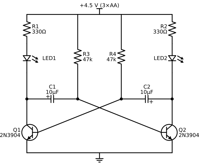
The circuit is two mirror-image halves. Each capacitor reaches across the "X" to the other transistor's base. Where the lines cross in the middle, there is no dot, so they are not connected.
The same connections as a list. Checking the build against a net list like this is good practice for the 11 y.o.:
| Net | Connects |
|---|---|
| +4.5 V | R1, R2, R3, R4 (top ends) |
| Q1 collector | LED1 cathode (−), C1 (+) |
| Q2 collector | LED2 cathode (−), C2 (+) |
| LED1 anode (+) | R1 |
| LED2 anode (+) | R2 |
| Q2 base | C1 (−), R3 |
| Q1 base | C2 (−), R4 |
| GND | Q1 emitter, Q2 emitter, battery (−) |
The schematic is generated from
blinker.py(schemdraw). Redrawing it in KiCad is a good 11 y.o. task after Unit 6.
Parts
| Qty | Part | Notes |
|---|---|---|
| 2 | 2N3904 NPN transistor | Flat face toward you, legs down: E B C from left to right |
| 2 | 5 mm LED | Two colors are more fun |
| 2 | 330 Ω resistor | orange-orange-brown. LED current ≈ (4.5 − 2) / 330 ≈ 7.5 mA |
| 2 | 47 kΩ resistor | yellow-violet-orange |
| 2 | 10 µF electrolytic capacitor, 16 V or more | The stripe marks − |
| 1 | 3×AA battery holder with switch | |
| 1 | Perfboard, about 5×7 cm | |
| — | Extra resistors for the practice board |
Jobs
| Step | 8 y.o. | 11 y.o. | Parent |
|---|---|---|---|
| Practice board | 10 joints with a parent beside | 20 joints plus a desolder drill | Coach, inspect |
| Sort and identify parts | Leads: finds resistors by color code | Checks each value with the meter | |
| LED + resistor on breadboard | Builds it | Measures the current, checks it with Ohm's law | |
| Blinker on breadboard | Places LEDs and batteries | Places everything else from the net list | Plants a fault later |
| Blinker soldered | Solders one side (Q1 half) | Solders the other side (Q2 half) | Inspection |
Steps
Session 1: joints
- Read Soldering Is Easy together.
- Practice board. Push resistor leads through the perfboard and bend them out slightly.
- Touch the iron to both the pad and the lead.
- Count 1–2, feed in solder, pull the solder away, then pull the iron away.
- A good joint looks like a shiny little volcano. A bad one is a ball, or dull and grainy.
- Clip the leads, holding the lead end so it doesn't fly.
- Swap boards and "grade" each other's joints. The 8 y.o. is a very strict inspector.
Session 2: breadboard, then solder
- On the breadboard: battery → 330 Ω → LED → battery. It lights.
- Flip the LED around. It doesn't light. Discuss why.
- Meter Reader: measure the battery and the voltage across the resistor. Compute the current as I = V / R.
- Build the blinker on the breadboard from the net list. Get it blinking before soldering.
- Move it to perfboard, one half each, mirrored left and right.
Session 3: debug and play
- The parent plants a fault (swaps an LED, lifts a joint). Kids find it with the meter. → Debugger badge.
- Experiment: swap one 10 µF for 47 µF and predict what happens before powering on. (That side stays on longer.)
Testing and troubleshooting
| Symptom | Likely cause | Check |
|---|---|---|
| Nothing lights | Battery backwards or dead; LED backwards | Meter on the battery; LED polarity |
| One LED stays on | A transistor is in wrong (EBC order) or a cap is backwards | Pinout; cap stripe toward the base side |
| Both LEDs on and dim | Missing cross-coupling; a cap isn't connected | Continuity from the cap to the other base |
| Blinks too fast or slow | Wrong resistor (4.7k vs 47k) | Color bands |
Level-ups
- Add a pot in series with R3 to adjust the blink rate.
- Swap the LEDs for a small speaker (with 100 Ω in series) and small caps (10 nF). It makes a tone. Same circuit, different speed. That's the bridge to Unit 4.
Talk about it
- Why did the bigger capacitor make that LED stay on longer?
- Where else have you seen things that blink back and forth? (Railroad crossings!)