Unit 5: Line Follower
A two-wheeled robot that follows a black tape track, with no code: just sensors, a comparator chip and transistors.
Sessions: 4–5 · Cost: ~$30 · Badges: Continuity Detective, Debugger Prerequisites: Units 3 and 4
Building it without a microcontroller first means the kids see the decision being made in hardware. Unit 9 adds a brain to the same chassis.
How it works (kid version)
- Two eyes look down at the floor. Each one shines invisible (infrared) light and sees how much bounces back. White bounces a lot; black tape bounces very little.
- The rule: if your eye sees white, your motor runs. If it sees black, your motor stops.
- The eyes straddle the line. When the line drifts under the left eye, the left motor stops and the right one keeps going, so the robot turns left, back onto the line.
- One simple rule, copied on both sides, makes it follow the line. That's emergent behavior.
How it works (grown-up version)
Each side has a TCRT5000 reflective sensor.
- The IR LED is fed through 330 Ω from about 6 V, so ≈ 15 mA.
- The phototransistor has a 10 kΩ pull-up to V+. Over white, it conducts and the collector goes low. Over black, the collector goes high.
- An LM393 compares the collector voltage (−, the inverting input) against a threshold pot (+).
- White: V− < Vref, so the open-collector output releases and a 10 kΩ pull-up takes it high.
- The high output switches on a logic-level N-MOSFET (IRLZ44N), which switches the motor's low side.
- Motor protection: a Schottky flyback diode (1N5819) across each motor, plus a 100 nF cap across its terminals for brush noise.
- The motors sit on the same side as their sensors.
One side (build two):
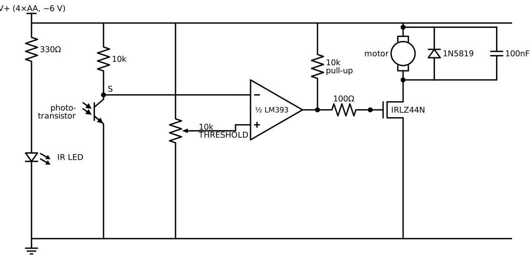
- Sensor: node S is low over white and high over black.
- Comparator: the output goes high when S < threshold, i.e. over white, and that turns the motor on.
- Put a 100 nF cap directly across each motor's terminals.
- The LM393 needs V+ on pin 8 and GND on pin 4, plus a 100 µF bulk cap across the supply.
Writing the full net list, from the breadboard version that works, is an 11 y.o. deliverable.
Parts
| Qty | Part | Notes |
|---|---|---|
| 1 | 2WD robot chassis kit with 2 TT gear motors, wheels and a caster | Or cardboard or 3D printed, with TT motors |
| 2 | TCRT5000 reflective IR sensor | Bare parts, not the modules (building it is the point) |
| 1 | LM393 dual comparator (DIP-8) and socket | |
| 2 | IRLZ44N logic-level MOSFET | Overkill, but nearly indestructible |
| 2 | 1N5819 Schottky diode | Flyback |
| 2 | 10 kΩ trimmer pot | One threshold per side |
| 2 | 330 Ω, 4 × 10 kΩ, 2 × 100 Ω (gate) resistors | |
| 2 | 100 nF ceramic | Across the motors |
| 1 | 100 µF electrolytic | Across the supply |
| 1 | 4×AA holder with switch | ≈ 6 V |
| 1 | Perfboard | |
| — | White poster board and black electrical tape | The track |
Jobs
| Step | 8 y.o. | 11 y.o. | Parent |
|---|---|---|---|
| Chassis assembly | Motors, wheels, screws | Battery mount, wire routing | |
| Sensor test on breadboard | Moves paper white/black while watching the meter | Reads the collector voltage and records a table | |
| Comparator + MOSFET on breadboard | Builds one side, then copies it | Checks it | |
| Solder the board | Solders the power LED, battery wires, motor wires | Solders the logic | Inspects |
| Track design | Designs and lays the tape track | Builds a "hard mode" track | |
| Tuning | Runs the stopwatch | Adjusts thresholds and sensor height |
Steps
- Sensor lab. Wire one TCRT5000. Measure the collector voltage over white paper, black tape and the table, at 3 mm and 10 mm height. Put the values in a table.
- This is the whole robot's "eyesight", so understand it before building the rest.
- One side on breadboard: sensor → LM393 → MOSFET → motor. Wave paper and watch the motor start and stop.
- Copy it for the other side.
- Transfer to perfboard and mount it. Sensors go about 5 mm above the floor, about 2 cm apart (a bit wider than the tape).
- Tune: set each threshold pot to halfway between its "white" and "black" voltages.
Testing and troubleshooting
| Symptom | Likely cause | Check |
|---|---|---|
| Motor never runs | MOSFET gate not reaching V+ | Meter at the gate over white |
| Motor always runs | Comparator inputs swapped | Sensor on (−), pot on (+) |
| Robot turns away from the line | Motors on the wrong sides | Swap the motor wires side to side |
| Overshoots and loses the line on curves | Too fast | Sensors further forward, lower battery voltage, gentler curves |
| Works in the kitchen, not by the window | Sunlight has lots of IR | Shield the sensors with black tape "blinders" |
| Chip resets when motors start | Supply sag or noise | 100 µF near the chip, 100 nF across the motors |
Level-ups
- PWM speed control: a 555 (Unit 4!) PWM feeding both gates.
- Unit 9: replace the LM393 with a Pico reading the sensors through its ADC. Then proportional steering becomes possible: that's PID, and a great "why is software powerful" lesson.
- A third, middle sensor for intersections.
Talk about it
- Where is the robot's "brain" in this circuit?
- What happens if both eyes see black at the same time? Is that a bug or a feature?