Unit 4: Punk Console
A two-knob noise synthesizer in a tin, built from two 555 timer chips.
Sessions: 3 · Cost: ~$15 · Badges: Chip Wrangler, Signal Spotter Prerequisites: Unit 1
This is Forrest Mims' "Stepped Tone Generator", better known as the Atari Punk Console (APC). One knob sets the pitch and the other sets the grit. It's loud and kids love it.
How it works (kid version)
- Chip 1 is a blinker, like Unit 1 but thousands of times faster. Blinking that fast makes a tone.
- Chip 2 is a "one-shot": each time chip 1 pokes it, it fires one pulse of a set length.
- When the pulse length and the poke speed don't match up, you get crunchy, stepped 8-bit-game sounds.
How it works (grown-up version)
IC1: astable oscillator. - R_A = 1 kΩ from Vcc to pin 7, R_B = a 500 kΩ pot from pin 7 to pins 2 and 6, C = 10 nF. - f = 1.44 / ((R_A + 2R_B)·C), which ranges from about 144 kHz (pot at 0) down to about 144 Hz (pot at 500 k).
IC2: monostable. - Triggered on each falling edge of IC1's output (trigger < ⅓Vcc). - Timing is 1 kΩ + 500 kΩ pot to pins 6 and 7, with C = 100 nF. - The pulse lasts t = 1.1·R·C, from about 0.11 ms to about 55 ms.
Why it sounds stepped: when t is longer than the trigger period, IC2 skips triggers and re-fires on the next edge after its timeout. The output frequency is therefore f_IC1 / n for integer n, and sweeping either pot jumps between integer divisions. Those jumps are the "steps".
Schematic
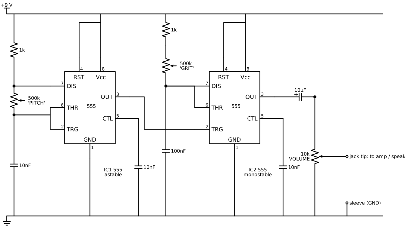
How to read it: - A dot means wires are joined. - Lines that cross without a dot are not connected. For example, the trigger wire crosses the GRIT column.
The 555 pinout, looking from the top with the notch up:
| Left side | Pin | Pin | Right side | |
|---|---|---|---|---|
| GND | 1 | ◖ notch | 8 | Vcc |
| TRIG | 2 | 7 | DISCH | |
| OUT | 3 | 6 | THRESH | |
| RESET | 4 | 5 | CTRL |
Output: the best sound comes from plugging into an amplified speaker. That can be the Unit 11 speaker's aux input later. Driving a small speaker directly needs a 100 Ω series resistor, which protects the 555 and the speaker, but it'll be quiet.
Parts
| Qty | Part | Notes |
|---|---|---|
| 2 | NE555 (DIP-8) | Or one NE556 (dual) for a smaller build |
| 2 | 8-pin DIP sockets | Always socket. The chips survive mistakes. |
| 2 | 500 kΩ linear pot (B500K) | Big knobs |
| 1 | 10 kΩ audio pot (A10K) | Volume |
| 3 | 1 kΩ resistor | Two for timing, one spare |
| 3 | 10 nF ceramic (103) | Timing and pin 5 bypass |
| 1 | 100 nF ceramic (104) | Timing |
| 1 | 100 µF electrolytic | Across the supply, near the chips |
| 1 | 10 µF electrolytic | Output coupling |
| 1 | 3.5 mm mono jack | |
| 1 | 9 V battery clip, SPDT switch, LED + 2.2 kΩ (power light) | |
| 1 | Perfboard and an enclosure (a mint tin, a cigar box, or a 3D print) |
Jobs
| Step | 8 y.o. | 11 y.o. | Parent |
|---|---|---|---|
| Breadboard prototype | Pot wiring, battery, speaker | 555 wiring from the schematic | Check before power |
| Socket soldering | One socket | One socket, then does the Chip Wrangler check | |
| Pots and jack wiring | Solders the pot leads | Solders the jack and switch | |
| Enclosure | Decorates, labels the knobs | Drills and marks the holes | Drilling metal tins |
| Scope it | Watches | Probes pin 3 of IC1 and IC2 | Sets up the scope |
Steps
Session 1: breadboard
- Build IC1 alone, with its output through the 10 µF to the speaker. Turn pot A: a pure tone rises and falls.
- Add IC2 and move the output to IC2's pin 3. Now there's crunch.
- Record a "song" on a phone. Seriously, it's the reward.
Session 2: solder
- Plan the layout on perfboard with a pencil on paper first. Mirror it for the copper side!
- Solder the sockets, then the passives, then the wires to the pots and jack.
- Before inserting the chips: power on, and meter pin 8 to pin 1 on each socket. It should read about 9 V.
- Insert the chips, notch matching the socket notch.
Session 3: enclosure and scope
- Mount everything in the tin, with electrical tape or a foam pad under the board so nothing shorts to the metal.
- Signal Spotter (use the parent's scope, or come back after Unit 8 with the scope the kids build): look at IC1 and IC2 outputs on a scope side by side while turning the knobs. The "skipped" pulses are visible.
Testing and troubleshooting
| Symptom | Likely cause | Check |
|---|---|---|
| Silent | Chip backwards; pin 4 (reset) floating or low | Notch; pin 4 at 9 V |
| Silent, chip hot | Chip backwards. Power off now! | Replace the chip if it's dead |
| Plain tone, no crunch | Output taken from IC1, not IC2 | Output wiring |
| Only clicks | 100 nF and 10 nF swapped | Cap markings: 104 vs 103 |
| Pot works backwards | Outer pot legs swapped | Swap them |
Level-ups
- Add a light sensor (an LDR in series with pot A) to make a "light theremin".
- Add a third 555 as a slow LFO wobbling IC1's pin 5 (control voltage).
- Unit 6 re-builds this on a board we etch ourselves.
Talk about it
- The chip is the same in both halves. What made one a blinker and one a one-shot?
- Why do you think it jumps in steps instead of sliding smoothly?