Unit 10: Servo Puppeteer
Turn a knob, and a servo follows. Then record a dance and play it back. Then build a little copy of the robot leg: move the copy with your hand, and the real leg copies you.
Sessions: 4–6 · Cost: ~$20 · Badges: Coder, Schematic Reader, (new) 🦾 Puppeteer Prerequisites: Units 4 and 9
Three stages. Each one stands alone, and each teaches what the next one builds on.
| Stage | What | Brains | Teaches |
|---|---|---|---|
| A | 555 servo tester | None: one 555 chip | What a servo signal is |
| B | 3 pots → 3 servos, plus record and playback | Pico | ADC, mapping, smoothing, lists as memory |
| C | Waldo: a replica leg with pots at its joints drives the real ~/legv2 leg |
Pico | Joint angles vs servo angles, calibration, coupling |
How servos work (kid version)
- A servo listens for a pulse every 20 ms (50 times a second).
- The length of the pulse says where to point:
- 0.5 ms = all the way one way
- 1.5 ms = middle
- 2.5 ms = all the way the other way
- Inside is a motor, gears, and a knob (a pot!) that tells the servo where it is. The servo keeps turning until its knob matches the pulse. Our controller is a pot talking to the servo's pot.
Stage A: the 555 servo tester (no code)
The Unit 4 chip again, as an astable with diode steering, so the high time and the low time are set separately.
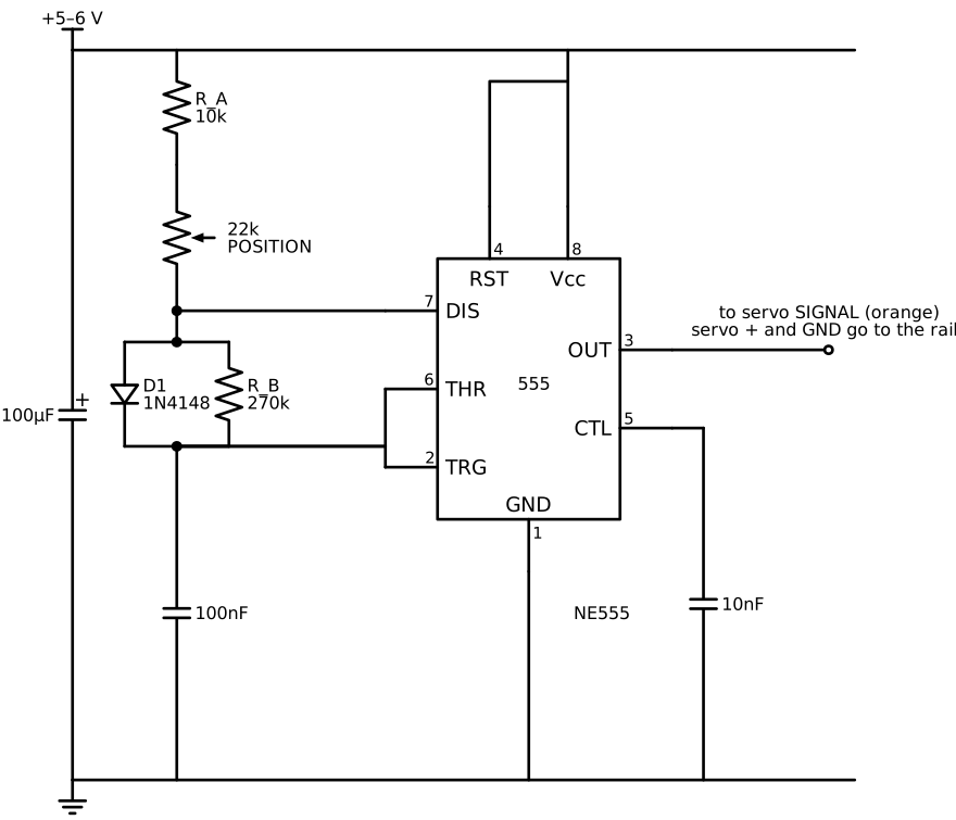
How the timing works:
| Phase | Current path | Time |
|---|---|---|
| Charge (output high = the pulse) | Vcc → R_A (10 kΩ + 22 kΩ pot) → pin 7 → D1 → C | t_H ≈ 0.693 · (10k…32k) · 100 nF ≈ 0.7–2.2 ms |
| Discharge (output low) | C → R_B (270 kΩ) → pin 7 → ground. D1 is reverse-biased. | t_L ≈ 0.693 · 270k · 100 nF ≈ 18.7 ms |
That gives a period of about 20 ms, or 50 Hz, which is what servos want. The diode drop stretches t_H a little, so trim with the pot.
We deliberately stop at 0.7–2.2 ms rather than 0.5–2.5 ms, so a cheap servo never gets driven into its end stop.
Parts
| Qty | Part |
|---|---|
| 1 | NE555 and a socket |
| 1 | 10 kΩ, 1 × 270 kΩ resistor |
| 1 | 22 kΩ linear pot (B22K), with a knob |
| 1 | 1N4148 diode |
| 1 | 100 nF film or ceramic (timing), 10 nF (pin 5), 100 µF (supply) |
| 1 | 3-pin male header for the servo plug |
| 1 | 4×AA holder (≈ 6 V) or the bench supply at 5 V |
Jobs
| Step | 8 y.o. | 11 y.o. | Parent |
|---|---|---|---|
| Breadboard | Plugs in the servo and turns the knob | Builds it from the schematic | Check before power |
| Scope it (Unit 8) | Watches the pulse get wider | Measures t_H at both pot ends and t_L | |
| Solder onto perfboard | Solders the header and battery leads | Everything else |
Keep it in the toolbox. A servo tester is how you check any servo before putting it in a robot: center it before you attach the horn.
Stage B: Pico puppeteer, 3 pots → 3 servos
flowchart LR
    subgraph ctrl [Controller box]
      p1[Pot 1]
      p2[Pot 2]
      p3[Pot 3]
      rec[REC button]
      play[PLAY button]
    end
    p1 -- GP26 --> pico[Pico]
    p2 -- GP27 --> pico
    p3 -- GP28 --> pico
    rec -- GP16 --> pico
    play -- GP9 --> pico
    pico -- GP10 --> s1((Servo 1))
    pico -- GP11 --> s2((Servo 2))
    pico -- GP12 --> s3((Servo 3))
    psu[Bench supply 5 V] -- "+5 V" --> s1 & s2 & s3
psu -. GND joined .- pico| Pico pin | Connects to |
|---|---|
| GP26 / GP27 / GP28 (ADC0–2) | Pot wipers. Pot ends go to 3V3 and GND, never 5 V. |
| GP10 / GP11 / GP12 | Servo signals |
| GP16 | Record button (to GND) |
| GP9 | Play button (to GND) |
| GP13 | Red LED (recording) |
| — | Servo power from the bench supply at 5 V. Join the grounds. |
The Pico has only 3 ADC pins we can use (ADC3 watches its own supply), so there are 3 pots. For more, add an ADS1115 or a 4051 multiplexer. That's a level-up.
Code: code/puppet.py. It needs ../09-microcontrollers/code/servo.py's
ideas, but it's self-contained.
- Smoothing: the ADC is noisy, so we low-pass filter it:
smooth += (raw - smooth) * 0.2. - Deadband: only move the servo when the target changes by at least 1°. No jitter.
- Record: hold the record button and every 20 ms the three angles get appended to a list. Release to stop.
- Play: press play and the list replays in a loop. Press it again to stop.
Build ideas
- Robot arm: 3 servos: base, shoulder, claw. Build it from popsicle sticks, cardboard, or a 3D print.
- Puppet show: a cardboard character whose head turns and whose mouth opens. Record the "performance", then play it back while the kids do the voices.
- Controller box: solder the pots and buttons into a box with big knobs. The 8 y.o. designs and labels the panel.
Jobs
| Step | 8 y.o. | 11 y.o. | Parent |
|---|---|---|---|
| Wire the pots | Plugs them in; turns them while watching the Shell print numbers | Maps 0–65535 → degrees | |
| Build the arm or puppet | Designs and builds it | Mounts the servos | Hot glue, cutting |
| Record a routine | Performs it | Adds a "speed" knob for playback | |
| Controller box | Panel art and labels | Solders it | Drills it |
Stage C: the Waldo (drives the real quadruped leg)
A waldo is a small replica that you move by hand, and the real machine copies it. The name comes from a 1942 sci-fi story.
- Build the replica at 1:1 from the leg geometry in
~/legv2. - Thigh 30 mm and calf 63–84 mm, joint to joint. See
~/legv2/README.md; the calf length is still being settled. - Cardboard or plywood, with a pot shaft as each joint: the hip pot fixed to a base, and the knee pot on the end of the thigh.
- The 8 y.o. can build most of this.
- The key idea: a joint angle is not a servo angle.
- The real leg's knee is driven through a linkage. From
~/legv2/calibration/cal_ch23.json, counting every angle as degrees moved from the zero pose:d_thigh = -0.936 × d_hip_servo d_calf = -0.700 × d_knee_servo + -0.111 × d_hip_servo ← coupling! - The waldo's pots measure the thigh and the knee. To make the real leg match, solve for
the servo angles:
d_hip_servo = d_thigh / -0.936 d_knee_servo = (d_calf - (-0.111 × d_hip_servo)) / -0.700 - A catch (the 11 y.o. and parent investigate this together):
- The calibration measured the calf's absolute angle in the camera image.
- The waldo's knee pot measures the relative angle (calf vs thigh).
- So
d_calf = d_thigh + d_knee, unless the camera's sign convention flips it.waldo.pyhas aCALF_IS_ABSOLUTEswitch. Test both, and record which one is right in the build log.
- This is the 11 y.o.'s big math moment: why does moving the hip make the knee move too, and how do we cancel it?
- Zeroing: put the waldo and the real leg in the same pose (the starting pose template,
~/legv2/starting_pose_1to1.pdf, printed 1:1) and press the button. Everything after that is measured relative to the zero. - Wiring:
- For the waldo session, unplug the leg's two servos from the Pi's PCA9685 HAT and plug them into the Pico (GP10 = hip, GP11 = knee).
legs.pyon the Pi has no joint-pose endpoint yet. AddingPOST /api/posewould let the Pico W drive the leg over WiFi instead. That's a good 11 y.o. + parent task later.
Code: code/waldo.py. The gains at the top come from the measured
ch2/ch3 calibration.
⚠️ The ch0/ch1 leg is not calibrated (see
~/legv2/README.md). Use the ch2/ch3 leg for the waldo, or measure ch0/ch1 first.
Jobs
| Step | 8 y.o. | 11 y.o. | Parent |
|---|---|---|---|
| Build the replica | Cuts, glues, mounts the pots | Measures the lengths against the real leg | |
| The coupling math | "Why does the foot wiggle when only the hip moves?" | Derives the servo equations from the gains | Explains the linkage |
| Tuning | Moves the waldo | Adjusts the gains and limits | Watches for binding and stalls |
Troubleshooting
| Symptom | Likely cause | Check |
|---|---|---|
| Servo jitters constantly | Noisy ADC or supply sag | Smoothing, deadband, 100 µF+ across the servo supply |
| Pico resets when servos move | Servos powered from the Pico | Separate supply, joined grounds |
| Servo buzzes and gets hot at one end | Pulse past the servo's mechanical stop | Narrow MIN_US/MAX_US or the angle limits |
| Pot reading jumps near the ends | Cheap pot, worn track | Use the middle of the pot's range |
| Waldo and real leg drift apart | Wrong zero, or a gain sign flipped | Re-zero at the template pose; check signs |
Talk about it
- The servo has a pot inside, and we're controlling it with a pot. What's the servo actually doing?
- Why does the real leg need different angles than the waldo, if they look the same?