Unit 7: Bench Power Supply
Our own adjustable lab supply: a voltage knob, a current-limit switch, a meter, and binding posts, on a board we etched ourselves. It powers every project from here on.
Sessions: 4–5 · Cost: ~$45 · Badges: Current Catcher, 🏭 Board Maker (second board), (new) 🌡️ Heat Manager Prerequisites: Unit 6
What we're building
A linear CC/CV supply:
- 1.25 V up to about 13 V (with a 19 V laptop brick) or about 18 V (with a 24 V brick)
- a switchable current limit of 20 mA / 100 mA / 500 mA / 1 A
- a built-in volt and amp display
Why current limiting matters: set 20 mA before powering a new build, and a backwards chip or a solder bridge just sits there harmlessly instead of cooking. It's the most useful tool on the bench.
⚠️ Mains safety
We don't build anything that touches 120 V. Input power comes from a sealed, certified laptop power brick (19–24 V DC). Nobody opens the brick. The DC side of this project is safe to work on with the brick unplugged.
How it works (kid version)
- A voltage regulator is a smart valve. It keeps the output pressure (voltage) steady no matter what you plug in.
- We use two of them:
- The first one says "never more than this much flow" (current).
- The second one says "always this much pressure" (voltage).
- Whatever voltage the valve doesn't pass on gets turned into heat. That's why it needs a big metal heatsink, and it's the big lesson of this unit.
How it works (grown-up version)
Two LM317s in series.
Stage 1, constant current (CC). - LM317 #1 has R_set between OUT and ADJ, and the load current is taken from ADJ. - The regulator holds 1.25 V across R_set, so I_lim = 1.25 / R_set. - A 4-position rotary switch picks R_set:
| Range | R_set | Actual I | P in R_set |
|---|---|---|---|
| 20 mA | 62 Ω | 20 mA | 25 mW |
| 100 mA | 12 Ω | 104 mA | 0.13 W |
| 500 mA | 2.4 Ω | 520 mA | 0.65 W (use a 2 W resistor) |
| 1 A | 1.2 Ω | 1.04 A | 1.3 W (use a 3 W resistor) |
Stage 2, constant voltage (CV). - LM317 #2 has R1 = 240 Ω (OUT→ADJ) and R2 = a 5 kΩ pot (ADJ→GND). - V_out = 1.25 · (1 + R2/R1), from 1.25 V up to the headroom limit. - The R1 divider draws about 5 mA, so the true output limit is I_lim − 5 mA.
Headroom. V_out,max ≈ V_in − 1.25 (R_set) − ~2 V (CC dropout) − ~2 V (CV dropout). - With a 19 V brick, that's about 13 V. - A diode for input polarity protection drops about 0.4 V more.
Heat, the core lesson. P ≈ (V_in − V_out) · I.
| Brick | Output | Current | Heat |
|---|---|---|---|
| 19 V | 3.3 V | 1 A | ~15 W, split between the two regulators |
| 19 V | 12 V | 1 A | ~7 W |
- With a TO-220 part (θjc ≈ 5 °C/W), an insulating pad (~1 °C/W) and a heatsink rated at 3 °C/W, 10 W in one regulator gives Tj ≈ 25 + 10 × 9 = 115 °C. That's near the limit.
- Mitigations:
- a large heatsink, plus a fan for the 1 A range
- a lower-voltage brick when you only need low voltages
- LM317s have built-in thermal shutdown, so overheating makes them cut out, not fail. That makes the lesson safe to learn.
- Level-up: a buck pre-regulator that tracks V_out + 4 V would kill most of the heat.
Protection. - 1N4002 from OUT to IN on each regulator, for when the input is shorted with charged caps on the output. - 1N4002 from ADJ to OUT on the CV stage, which discharges the 10 µF ADJ bypass cap. - A Schottky diode in series with the input, for reverse-polarity protection.
Schematic
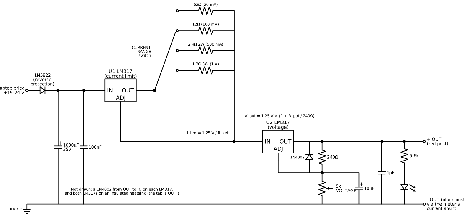
The CC stage in words: input → LM317#1 IN. LM317#1 OUT → rotary switch common. Each switch position → one R_set → joined together at LM317#1 ADJ. LM317#1 ADJ → LM317#2 IN.
Parts
| Qty | Part | Notes |
|---|---|---|
| 1 | Laptop power brick, 19–24 V, ≥ 65 W | Many families have a spare one. Match the barrel jack. |
| 2 | LM317T (TO-220) | Buy spares |
| 1 | Heatsink, ≤ 3 °C/W, plus 2 insulating pads and shoulder washers | The LM317 tab is OUT, not ground. Insulate both! |
| 1 | 40 mm 12 V fan (optional; feed it via a 7812 or a resistor from the input) | |
| 1 | 1P4T rotary switch and knob | Current range |
| 4 | R_set: 62 Ω ¼ W, 12 Ω ½ W, 2.4 Ω 2 W, 1.2 Ω 3 W | |
| 1 | 5 kΩ linear pot (a 10-turn pot is a luxury upgrade) | Voltage |
| 1 | 240 Ω resistor | |
| 3 | 1N4002 diodes; 1 × 1N5822 Schottky | Protection |
| — | Caps: 1000 µF 35 V, 2 × 100 nF, 10 µF 25 V, 1 µF 25 V (or 10 µF) | Input, output, ADJ bypass |
| 1 | Dual volt/amp panel meter module (e.g. "0–100 V 10 A") | Follow its wiring diagram: thin = power + sense, thick = shunt |
| 1 | Pair of 4 mm binding posts (red and black), DPST output switch, power LED + 5.6 kΩ | |
| 1 | Barrel jack for the brick | |
| 1 | Enclosure: plywood box, aluminum project box, or a 3D print | Needs vents |
Jobs
| Step | 8 y.o. | 11 y.o. | Parent |
|---|---|---|---|
| Breadboard CV stage alone (low current) | Turns the knob, reads the meter, fills in a volts-per-knob-mark table | Wires it, checks it against the formula | |
| KiCad + etch the board | Front-panel artwork and labels | Schematic + layout | Etchant |
| Heatsink mounting | Screws, fan | Insulating pads; checks tab-to-heatsink isolation with the meter | Verifies it |
| Front panel | Designs the label and marks the holes | Wires the switch, pot and meter | Drills the panel |
| Test day | Records the table | Runs the tests | Supervises |
Test procedure (with a dummy load)
Make a dummy load from a couple of 10 Ω 10 W power resistors, or a car bulb.
- No load: sweep the voltage knob and record the min and max V.
- 20 mA range, short the output with a wire: the meter reads about 20 mA and nothing gets hot. This is the "it protects my projects" moment.
- Repeat the short on each range and record the actual current.
- Load regulation: set 5 V and apply 10 Ω (0.5 A). How far does the voltage drop?
- Heat test: 3.3 V into 3.3 Ω at 1 A. Time how long until the heatsink is too hot to touch, or until the output cuts out. Heat Manager badge: explain why using P = (Vin − Vout) · I.
Testing and troubleshooting
| Symptom | Likely cause | Check |
|---|---|---|
| Output stuck at about V_in | CV ADJ open; pot wiper not connected | ADJ-to-ground resistance |
| Output 1.25 V only | Pot shorted, or wired end-to-wiper wrong | Pot wiring |
| Current limit doesn't work | Load taken from LM317#1 OUT instead of ADJ | CC wiring |
| Dead after touching the heatsink to the case | Tab (OUT) shorted through an uninsulated mount | Meter: tab to heatsink should be open |
| Meter reads current wrong | Shunt in the wrong lead | Follow the module diagram |
Level-ups
- Tracking buck pre-regulator: an LM2596 module whose feedback is set to about V_out + 4 V. That cuts heat by about 5×.
- Variable current limit: replace the switch with an op-amp + sense resistor CC loop.
- Digital: a Pico reads V and I with its ADC and shows them on the Unit 9 LCD.
- Compare: buy a DPS5005-style module and compare noise on the Unit 8 scope. Linear is quieter, switching is cooler. Discuss.
Talk about it
- Where did the "missing" volts go when the output was 3.3 V and the input was 19 V?
- Why is a current limit better than a fuse for experimenting?