Unit 16: Micro RC Cars
A small RC car per kid, built from LEGO Technic and cheap modules, with real rack-and-pinion steering and a differential.
- Park it on its wireless charging pad to recharge. No battery packs to pull out.
- Plug-in modules add lights, a distance sensor, a camera, and a self-driving "robot" mode.
- The kids build the controller too.
Sessions: 10–14 (spread over weeks) · Cost: ~$40–70 per car, ~$20 controller, ~$20 pad · Badges: Tiny Parts, Coder, Heat Manager, (new) 🏎️ Pit Crew Prerequisites: Units 9 (Pico/ESP basics), 10 (servos), 11 (Li-ion safety). Unit 5 (MOTOR switching) and 12 (radio ideas) help.
Commercial kits like this exist, but they cost a lot and hide the interesting parts. Here every block is something we've already met in an earlier unit, now combined.
The system
flowchart LR
    subgraph ctl [Controller]
      sticks[2 thumb sticks<br/>+ 3 buttons] --> cesp[ESP32]
      cesp --> oled[OLED:<br/>battery, distance, mode]
    end
    subgraph car [Car]
      xiao[XIAO ESP32S3] --> drv[DRV8833] --> mot((Drive motor<br/>→ differential))
      xiao --> srv((Steering servo<br/>→ rack & pinion))
      xiao --> leds[Head / tail /<br/>turn LEDs]
      tof[Distance sensor] --> xiao
      cam[Camera<br/>Sense board] -.-> xiao
      pi[Pi Zero 2 W<br/>brain module] <-. UART .-> xiao
      qirx[Qi receiver coil] --> chg[Charger +<br/>load sharing] --> bat[(1S LiPo)]
    end
    subgraph pad [Charging pad 'garage']
      qitx[Qi phone<br/>charging pad]
      pesp[ESP32 + LED ring<br/>fuel gauge]
    end
    cesp <-- "ESP-NOW<br/>control 50 Hz / telemetry 5 Hz" --> xiao
    xiao -- telemetry --> pesp
qitx -. magnetic field .-> qirx- ESP-NOW is Espressif's router-free, low-latency radio link.
- Broadcast plus a car ID means several cars and controllers share the air without pairing: controller #2 drives car #2 only.
Part 1: chassis (no 3D printing)
| Option | Steering | Differential | Motor coupling | Good for |
|---|---|---|---|---|
| A. LEGO Technic (recommended) | Technic gear rack + 8-tooth pinion + steering knuckles | Technic differential with 3 bevel gears inside | GeekServo motor and servo: they have LEGO cross-axle outputs and pin holes | Kids redesign it endlessly. Nothing is glued. |
| B. Thrift-store toy RC car as a donor | Keep it if it's proportional (a servo, or a motor + pot). Many cheap cars use "bang-bang" magnet steering, which you replace with a servo and a paperclip linkage. | Usually present | Keep the car's own motor and gearbox | Fastest start; teaches reverse engineering |
| C. Hardware-store scratch build | Plastic M0.5 gear rack + pinion strips, brass tube kingpins | Skip it, and use two motors as an "electronic differential" (twist!) | N20 gear motors, zip ties, hot glue | Plywood or aluminum-flat-bar chassis fans |
Getting LEGO parts cheaply
- A used Technic car set, or bulk Technic sold by the pound (thrift stores, eBay, Facebook Marketplace), usually already contains a steering rack, knuckles, and a differential.
- Missing pieces cost cents each on BrickLink or LEGO Pick a Brick. Search "Technic differential", "Technic gear rack", "Technic steering".
- Kids should design the chassis themselves. The rules:
- Steering servo → pinion → rack → both front wheels.
- Drive motor → gear down (e.g. 8T driving 24T, 3:1) → differential → rear wheels.
- Leave a flat, open area under the floor for the Qi receiver coil. The coil is a thin disc about 40–50 mm across.
- Keep the battery away from the coil (at least 1 cm up). Metal near the coil heats up.
GeekServo (Kittenbot) parts: - a 9 g-class servo (270° or 360° versions) - a DC gear motor
Both have LEGO-compatible cross-axle outputs and Technic pin mounting holes. Check the listing for the voltage range; they're sold for 3.3–6 V builds.
Twist: the electronic differential (option C, or a level-up for A). - Drive each rear wheel with its own N20 motor, using both channels of the DRV8833. - The firmware slows the inside wheel in turns, which is what a mechanical differential does, and more. - It's a great 11 y.o. lesson: what does a differential actually do? Take the LEGO one apart and watch the bevel gears.
Scale check
A LEGO Technic car with an ESP32 board and a small LiPo lands around 15–20 cm long, closer to 1:18 than a 1:28 Mini-Z. That's fine, and easier for small hands to build and fix. For truly tiny (option C with N20s and a XIAO), about 10 cm is doable.
Part 2: car electronics
Parts per car
| Qty | Part | ~$ | Notes |
|---|---|---|---|
| 1 | Seeed XIAO ESP32S3, or the XIAO ESP32S3 Sense (adds a camera and microSD) | 8 / 14 | Thumb-sized. The Sense is only needed for the camera stage. |
| 1 | DRV8833 dual H-bridge breakout | 2 | 2.7–10.8 V, happy on 1S. One channel for the drive motor; both for the electronic differential. |
| 1 | GeekServo DC motor, or an N20 gear motor (~300 RPM at 6 V) | 5 | |
| 1 | GeekServo or SG90 micro servo | 4 | Steering |
| 1 | 1S LiPo, 500–1000 mAh, with a protection circuit | 6 | |
| 1 | TP4056 USB-C charger board with DW01 protection (6-pin: IN, OUT, B) | 1 | Set the charge current. See the power section. |
| 1 | Qi receiver patch (the kind sold to add wireless charging to old phones; 5 V out) | 4 | |
| 1 | AO3401 P-MOSFET (SOT-23), SS14 Schottky, 3 × 100 kΩ + 2 × 100 kΩ | 1 | Load sharing and sensing. Tiny Parts badge material. |
| 1 | Slide switch | 0.5 | Main power |
| 4 | WS2812B LEDs (on a strip you can cut, or as single "pixels") | 1 | 2 front, 2 rear |
| 1 | VL53L1X laser distance sensor (I2C), or an RCWL-1601 ultrasonic (a 3.3 V HC-SR04 twin) | 5 / 3 | The laser one is tiny and good on small cars. The ultrasonic continues Unit 9. |
| — | JST-PH 2.0 mm connectors, perfboard, hookup wire | 3 | The module ports |
Module ports: the "standard plug" idea
The car's main board is perfboard, or an etched board (Unit 6), with the XIAO in the middle and keyed JST-PH sockets around the edge. Every add-on is a module with a matching plug, so kids can swap and invent modules without re-soldering the car.
| Port | Pins | XIAO pins | Used by |
|---|---|---|---|
| DRIVE | 2 (motor + / −) | D0, D1 → DRV8833 AIN1/AIN2 | Drive motor |
| DRIVE2 | 2 | D6, D7 → DRV8833 BIN1/BIN2 | Second motor (electronic differential). Needs firmware changes. Uses the SONAR/BRAIN pins, so a two-motor car uses the VL53L1X and no brain, unless you add an I2C GPIO expander. |
| STEER | 3 (SYS, GND, signal) | D2 | Steering servo |
| LIGHTS | 3 (SYS, GND, data) | D3 | WS2812 chain: 0 = front-left, 1 = front-right, 2 = rear-left, 3 = rear-right |
| I2C | 4 (3V3, GND, SDA, SCL) | D4, D5 | VL53L1X, or later an IMU or a small OLED. Same order as Qwiic/STEMMA QT, so those modules fit with an adapter cable. |
| SONAR | 4 (3V3, GND, TRIG, ECHO) | D6, D7 | RCWL-1601 ultrasonic |
| BRAIN | 4 (EN, GND, TX, RX) | D10 (5 V boost enable), D6 → Pi RXD, D7 ← Pi TXD | Pi Zero 2 W brain module (Part 6). It shares D6/D7 with SONAR, so a brain car uses the VL53L1X. |
| CHARGE | 2 | — | Qi receiver patch → charger board |
| (internal) | — | D8, D9 | Battery voltage and charge-detect dividers |
Camera: on the XIAO ESP32S3 Sense, the camera is a clip-on board with its own connector, so it uses none of D0–D10.
Power path and wireless charging
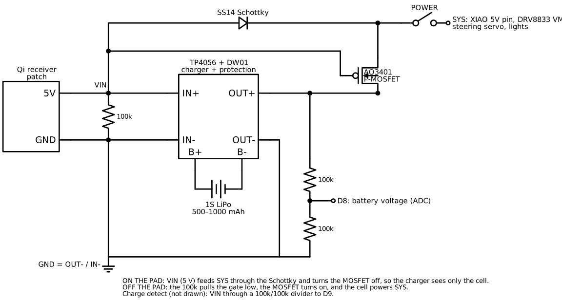
Why the "load sharing" parts?
- A TP4056 decides the battery is full when the charge current drops low.
- If the car's electronics are drawing current from the battery at the same time, the charger never sees that drop. It can keep charging forever, which is bad for a LiPo.
- The Schottky + P-MOSFET pair fixes this. On the pad, the car runs from the pad's 5 V and the battery is only being charged. Off the pad, the MOSFET switches the battery back in automatically.
- Explaining this is a great 11 y.o. exercise.
Two traps with these modules: - The protected ground is OUT− / IN−, not B−. The DW01 protection switch sits in the negative lead. If you connect the car's ground to B−, you bypass the protection. - Charge current is set by the board's R_PROG resistor: I ≈ 1200 / R_PROG(kΩ) mA.
| R_PROG | Charge current | Use with |
|---|---|---|
| 1.2 kΩ (usual default) | ~1 A | ≥ 1000 mAh cell, and only if the Qi patch can supply it |
| 2.4 kΩ | ~500 mA | 500–1000 mAh (recommended) |
| 4.7 kΩ | ~250 mA | Small cells, or a weak Qi patch |
Realistic numbers: - Qi links are roughly 50–70 % efficient. - A 600 mAh cell at 500 mA takes about 1.5 h from empty. - Driving time is about 20–40 minutes, depending on the motor.
The charging "garage"
Qi only works when the coils are close (a few mm) and lined up (within ~5–10 mm). So the pad is built into a little garage that lines the car up for you:
flowchart LR
    ramp[Entry ramp] --> lanes[Two wheel lanes<br/>with side curbs] --> stop[Back stop block]
    pad[Qi pad raised between the lanes,<br/>its top just under the car's floor] --- lanes
ring[LED ring 'fuel gauge'<br/>on the back wall] --- stop- Side curbs (wood strips, or LEGO) center the car left to right.
- The back stop sets front to back. Drive in until you touch it.
- The Qi pad sits in the middle, raised on shims so the car's coil ends up about 2–4 mm above it. Fine-tune the height with cardstock shims and watch the charge-detect LED.
- Use a real, certified Qi phone charging pad. Those detect foreign metal objects and refuse to heat a coin or a key. The bare "wireless power module" coil pairs sold online often don't have that protection.
How you know it's charging:
- The car's 4 lights become a battery gauge: green bars filling up, with the top one
pulsing.
- The pad's LED ring (firmware/pad/) shows the same level, big enough to see
across the room.
- The controller's OLED shows CHARGING and the percentage.
Plan B, if the Qi alignment is too fiddly: contact charging. - Copper-tape rails on the garage floor, with spring contacts on the car. This is how robot vacuums dock. - It's cheaper and more efficient, and still means no unplugging. - The load-sharing circuit is identical. Only the 5 V source changes.
⚠️ Battery safety
The Unit 11 rules apply. - Protected cells only. - Charge while someone's home. - A puffy cell gets retired. - Car crashes are impact tests for the battery: mount it in the middle of the chassis, padded with foam tape, never at the bumper.
Part 3: the controller
The kids build this from scratch.
| Part | Notes |
|---|---|
| ESP32 devkit (classic ESP32-WROOM-32) | Any ESP32 works for ESP-NOW |
| 2 × thumb-joystick modules (KY-023 style) | Power them from 3.3 V, not 5 V |
| 3 pushbuttons | MODE, LIGHTS, CAR # |
| SSD1306 128×64 I2C OLED | Telemetry display |
| 18650 cell + holder + TP4056/protection + boost to 5 V, or 3×AA | The same power skills as Unit 11 |
| Enclosure | Plywood box, a cigar box, a mint tin, or LEGO |
Wiring is at the top of firmware/controller/controller.ino.
Important: the sticks must use ADC1 pins (GPIO32–39). ADC2 stops working whenever the radio is on.
Controls: - Left stick up and down = throttle. Right stick left and right = steering. - MODE cycles through DRIVE, SAFE and ROBOT (explained below). - LIGHTS toggles the lights. - CAR # picks which car this controller drives (remembered after power-off).
Part 4: firmware
| Sketch | Board | Libraries |
|---|---|---|
firmware/car/car.ino |
XIAO ESP32S3 | Adafruit NeoPixel, Pololu VL53L1X |
firmware/controller/controller.ino |
ESP32 Dev Module | Adafruit SSD1306, Adafruit GFX |
firmware/pad/pad.ino |
Any ESP32 (C3 SuperMini is great) | Adafruit NeoPixel |
- Core: Arduino IDE or
arduino-cliwith the esp32 core 3.x (Espressif). - Shared protocol: each sketch folder has an identical
protocol.h(the packet formats). After editing one, copy it to the others.tools/check_protocol.shchecks they match. - Before the first drive, set in
car.ino: CAR_IDUSE_TOF(1 = laser distance sensor, 0 = ultrasonic)STEER_CENTER_US: trim until the car tracks straightSTEER_RANGE_US: stop just before the rack hits its ends
Drive modes
| Mode | Name on the OLED | What the car does |
|---|---|---|
MODE_MANUAL |
DRIVE | You drive. Throttle is capped at MAX_THROTTLE (start at 50–80 % for the 8 y.o.). |
MODE_AVOID |
SAFE | You drive, but the car refuses to go forward within 25 cm of an obstacle and flashes its hazards. Reverse still works. |
MODE_AUTO |
ROBOT | The car drives itself. It cruises, and when something is within 40 cm it does a 3-point turn, alternating sides. Pull the throttle stick back to stop it. |
MODE_BRAIN |
BRAIN | The Pi brain module drives (Part 6). Any stick movement overrides it instantly. The car stops if the Pi goes quiet for 300 ms. |
Built-in safety
- Failsafe: no packet for 400 ms → the motor stops and the hazards flash. Turn the controller off mid-drive and the car stops by itself. Test this first!
- Low battery (< 3.45 V): half speed plus hazards. "Limp home to the pad."
- Throttle ramping protects the LEGO gears from sudden reversal.
- On the pad, driving is disabled.
The lights are automatic
- Headlights when lights are on.
- Brake lights when slowing or reversing.
- Turn signals on hard steering.
- Hazards on failsafe, low battery, or a SAFE-mode stop.
The 8 y.o. can own the light patterns: colors and blink rates are easy, safe code edits.
Part 5: camera (Sense board)
- First, alone: flash Espressif's
CameraWebServerexample (File → Examples → ESP32 → Camera) with the XIAO ESP32S3 Sense camera model selected. Open the stream on a phone or laptop. - Mount it on the car's nose with a LEGO hinge, so the tilt is adjustable.
- Combine it with
car.ino(an 11 y.o. + parent project): - The camera needs WiFi (join the home network, or have the car be an access point), and ESP-NOW has to share that radio.
- All three devices must use the same WiFi channel. Set
WIFI_CHANNELinprotocol.hto the AP's channel. - Expect ~100–300 ms of video lag. That's fine for exploring, but drive slowly "first-person".
Level-up: stream to a laptop, find a colored ball with OpenCV, and send steering commands back. The car chases the ball.
Part 6: brain module (Raspberry Pi Zero 2 W)
The XIAO is great at real-time jobs, but too small for computer vision, lidar, or heavy math. So the brain rides on the car as one more module:
| Job | Done by |
|---|---|
| Motors, steering, radio link, lights, every failsafe | XIAO: the "spinal cord" |
| Camera vision (OpenCV), lidar, IMU, planning, logging, a web dashboard | Pi: the "brain" |
- The Pi only suggests throttle and steering over a serial line. The XIAO decides whether to obey.
- If the Pi crashes, hangs, or is still booting, the car just stops. The controller must stay on as the dead-man switch, and any stick movement overrides the brain.
Zero 2 W vs the original Zero W: use the Zero 2 W. It's the same size and connectors, but quad-core and about 5× faster, which is the difference between OpenCV being usable and not. The original Zero W works for lighter jobs (logging, a dashboard, a few frames per second).
Wiring and power
flowchart LR
    sys[SYS 3.0–4.7 V] --> boost[5 V boost, ≥ 1.5 A,<br/>with an EN pin] --> pi[Pi Zero 2 W<br/>5V + GND pins]
    xiao[XIAO] -- "D10 → EN" --> boost
    xiao -- "D6 TX → GPIO15 RXD" --> pi
    pi -- "GPIO14 TXD → D7 RX" --> xiao
    cam[Pi Camera<br/>Zero-size ribbon] --> pi
extra[Lidar / IMU / GPS …] -.-> pi- The Pi needs a steady 5 V. Use a boost converter from SYS with an enable pin, e.g. a Pololu U3V16F5 or any boost board with EN. That lets the XIAO power the Pi down.
- Both boards are 3.3 V logic, so the UART wires connect directly.
- Bigger battery: the Pi draws about 0.3–0.6 A at 5 V (≈ 0.5–1 A from the cell). Move to a 1500–2000 mAh 1S pack. Expect about 45–90 min of driving.
- On the pad: the Pi plus the charger both draw from the Qi patch, which gives ~1 A at best. Set R_PROG to 4.7 kΩ (250 mA), or have the brain idle while it charges.
- Shutting down safely: cutting power to a running Pi can corrupt its SD card.
- When the battery stays below 3.5 V for 5 s, the XIAO sends
S.carlink.pyrunsshutdown, and the XIAO cuts the boost 20 s later. - Also turn on Raspberry Pi OS's read-only overlay file system (
raspi-config→ Performance). Then a surprise power cut can't hurt the card.
Pi setup
- Flash Raspberry Pi OS Lite (64-bit). Set WiFi, SSH and a user in Raspberry Pi Imager.
sudo raspi-config: Interface → Serial Port → login shell No, hardware Yes.- In
/boot/firmware/config.txt, adddtoverlay=disable-bt. That gives/dev/serial0the good UART (PL011) instead of the mini-UART, whose baud rate drifts with the CPU clock. sudo apt install python3-opencv python3-picamera2 python3-serial- Copy
brain/to the Pi. On the car, setHAS_BRAIN 1incar.inoand reflash it.
The code (brain/)
| File | What |
|---|---|
carlink.py |
The serial protocol: drive(throttle, steer), telemetry (battery, distance, charging, mode), and the shutdown request. test_carlink.py tests it on any computer. |
camera.py |
Frames from the Pi camera as OpenCV images |
line_follow.py |
Demo 1: follow black tape with the camera (PD steering). The same idea as Unit 5, but the "sensor" is 76,800 pixels. |
dock.py |
Demo 2, self-parking: find the ArUco marker on the garage wall, drive in, creep the last bit, and stop when the car reports charging. |
make_marker.py |
Prints the ArUco marker for the garage wall |
Self-parking closes the loop on the whole project: drive around → battery low → it
parks itself on the charger. The 11 y.o. can combine dock.py with the battery
telemetry: "if battery < 30 %, go dock".
What else the brain opens up
- 2D lidar (LDRobot LD06/LD19 class, ~$70–100): a 360° distance scan. Map the room and plan paths.
- Connect it through a USB-serial adapter on the Zero's USB port, since the UART belongs to the XIAO.
- IMU (BNO055, MPU-6050) on the Pi's I2C: heading, and detecting crashes and flips.
- Web dashboard: a live camera feed plus telemetry graphs on a phone, served by the Pi.
- Machine learning: TensorFlow Lite object detection at a few frames per second on a Zero 2 W. Stop signs made from LEGO!
- Logging: record every drive (telemetry + video). Then replay it and discuss what the robot "saw".
Jobs
| Step | 8 y.o. | 11 y.o. | Parent |
|---|---|---|---|
| Chassis design | Designs and builds the LEGO chassis | Gear ratio math, steering geometry | Checks the rack doesn't bind |
| Motor and servo mounting | Mounts the GeekServo parts | Centers the servo with the Unit 10 tester before attaching the pinion | |
| Car main board | Solders the JST sockets and the switch | Solders the XIAO headers, DRV8833, dividers; the MOSFET and Schottky (Tiny Parts) | Power path check with the bench supply, before a battery goes in |
| Charger + Qi patch | Wires it; sets R_PROG | Battery connection | |
| Garage | Builds it (wood or LEGO), paints it, adds the LED ring | Tunes the pad height with shims | Qi pad choice |
| Controller | Buttons, box, labels | Sticks, OLED, firmware flash | |
| Firmware | Changes light colors, MAX_THROTTLE, car name/ID |
Trims steering, tunes the avoid distances, writes new auto behaviors | Code review |
| Test day | Obstacle course designer | Failsafe test | Referee |
Suggested session plan
- Chassis: steering and drive by hand, no electronics. Does it roll straight? Does the diff work? (Lift a wheel and spin the other.)
- Motor + servo on the bench supply: XIAO + DRV8833 + servo on a breadboard, driven from a USB serial test sketch.
- Controller: build it, flash it, watch the OLED numbers change.
- First drive, powered from the bench supply through long thin wires (current limit 1 A). There's no battery risk yet.
- Power path: build the charger and load-sharing on the bench and measure it before connecting the LiPo (below).
- Battery in; first untethered drive. Then the failsafe test.
- Lights module.
- Distance module; SAFE and ROBOT modes.
- Garage + Qi. Tune the alignment.
- Pad LED ring; first "drive in, watch it charge, drive out".
- Camera (optional).
- Race day: both kids' cars, lap timing, an obstacle course.
Power path bench test (before any LiPo is connected)
Use the Unit 7 supply in place of the battery (3.7 V, 200 mA limit) and a USB 5 V source in place of the Qi patch.
| Test | Expect |
|---|---|
| "Battery" only | SYS ≈ 3.7 V (through the MOSFET); D9 reads LOW |
| 5 V applied | SYS ≈ 4.6–4.7 V (through the Schottky); D9 HIGH; the MOSFET gate is at 5 V, so it's off |
| 5 V applied, SYS loaded with 100 Ω | The supply standing in for the battery shows no current flowing out of it into SYS |
| D8 | ≈ half the "battery" voltage |
Troubleshooting
| Symptom | Likely cause | Check |
|---|---|---|
| Car doesn't respond | Wrong CAR_ID, or a channel mismatch |
Controller OLED says "no signal"; compare CAR_ID with the CAR # |
| Stutters, resets when the motor starts | Battery sag or motor noise browning out the XIAO | 470 µF across SYS; 100 nF across the motor terminals; twist the motor wires |
| Steering pulls to one side | Servo not centered | STEER_CENTER_US |
| Servo buzzes at full lock | The rack is at its end stop | Reduce STEER_RANGE_US |
| Never shows CHARGING on the pad | The coils are too far apart or not lined up | Shim the pad up; measure VIN on the car |
| Charges, but never reaches 100 % / TP4056 never shows "full" | Load sharing isn't working | Measure the MOSFET gate on the pad: it should be ≈ 5 V |
| Pad or car coil gets hot | Metal near the coil (screws, battery) | Move the battery up; nylon screws near the coil |
| Distance always "--" | Sensor not found (I2C), or the wrong USE_TOF |
Serial monitor at boot |
| Controller sticks drift | Center calibrated while a stick was touched | Power-cycle hands-off |
| BRAIN mode just flashes hazards | The Pi isn't sending C lines (still booting, the script isn't running, or the UART isn't set up) |
On the Pi: python3 -c "from carlink import CarLink; import time; c=CarLink(); time.sleep(1); print(c.telemetry)" |
| Garbled serial | The mini-UART is active | dtoverlay=disable-bt, then reboot |
Level-ups
- Electronic differential with two motors.
- Line following: a Unit 5 TCRT5000 pair as a module on the I2C port (through an ADS1115) or on spare pins.
- Lap timer: an IR beam across the track (Unit 3's timing gate), reporting to the pad over ESP-NOW. The pad's ring flashes the winner's color.
- Self-parking: in ROBOT mode, when the battery is low, find the garage. (Hard! Needs a beacon: an IR LED on the garage, or a colored target plus the camera.)
- Horn/sound module: a small buzzer on a spare pin. Unit 9's
songs.pyideas, ported to C++. - Radio remote tie-in: the Unit 12 DTMF bridge could "call" a car home.
Talk about it
- The car stops when it loses the controller. Why is that the right choice? What do real self-driving cars do?
- Why is charging without plugging in less efficient? Where does the missing energy go?
- A mechanical differential and an "electronic" one do the same job. Which is better, and why do real cars use both?