Unit 2: Crystal Radio
Pull music and voices out of the air with a coil, a wire and a diode. No battery.
Sessions: 2 · Cost: ~$15 · Badges: Wire Wrangler (optional) Prerequisites: Unit 1
The 8 y.o. leads this one. There's hardly any soldering, lots of winding and a big "whoa" moment.
What we're building
A tuned-circuit AM receiver:
- a hand-wound coil on a cardboard tube,
- a variable capacitor to tune it,
- a germanium diode to "detect" the audio,
- a crystal earpiece to hear it.
All the power comes from the radio station's own signal.
How it works (kid version)
- AM stations send out invisible waves. Your antenna wire catches a tiny bit of all of them.
- The coil and capacitor are like a swing: they only swing big at one "rhythm" (frequency). Turning the knob changes the rhythm, so you pick one station.
- The diode is a one-way door. It chops the wave in half so the earpiece can follow the slower wiggle, which is the voice or music.
How it works (grown-up version)
The LC tank resonates at f = 1 / (2π√(LC)).
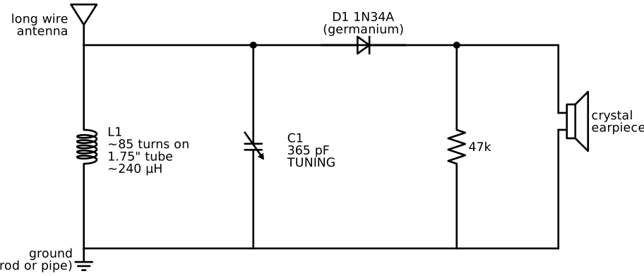
Coil: - About 85 turns of 26 AWG enameled wire, close-wound on a 1.75" (4.4 cm) tube. - Wheeler's formula, L(µH) = r²N² / (9r + 10ℓ), with r = 0.875" and ℓ ≈ 1.5", gives L ≈ 240 µH.
Tuning range with a 365 pF variable capacitor:
| Capacitor setting | Capacitance | Frequency |
|---|---|---|
| Fully meshed | 365 pF | ≈ 540 kHz |
| Open | ~45 pF, including stray | ≈ 1.5 MHz |
That covers most of the US AM band (530–1700 kHz).
Detector: - A germanium diode (1N34A), because its forward drop is ~0.2–0.3 V against ~0.6 V for silicon. It matters at these tiny signal levels. - A crystal earpiece is high impedance. Put a 47–100 kΩ resistor across it to give the diode a DC return path.
Parts
| Qty | Part | Notes |
|---|---|---|
| 1 | Toilet paper or paper towel tube, ~1.75" diameter | Or PVC pipe |
| ~50 ft | 26 AWG magnet wire | Scrape the enamel off the ends with sandpaper |
| 1 | 365 pF variable capacitor | Air variable or polyvaricon. Often sold as "crystal radio tuning cap". |
| 1 | 1N34A germanium diode | |
| 1 | Crystal (piezo) earpiece | Not a regular headphone. Those are too low impedance. |
| 1 | 47 kΩ resistor | Across the earpiece |
| 1 | Wood board, screws and Fahnestock clips or screw terminals | A "breadboard" in the original sense |
| 50–100 ft | Insulated wire for the antenna | Longer and higher is better |
| 1 | Ground: a clamp on a metal cold-water pipe, or a 4 ft ground rod |
Jobs
| Step | 8 y.o. | 11 y.o. | Parent |
|---|---|---|---|
| Wind the coil | Winds it, counting turns out loud | Holds the tube, tapes the ends | |
| Mount parts on the board | Screws in the terminals | Wires and solders the diode and earpiece leads | |
| Antenna | Carries the wire and picks the tree | Measures the length and ties the insulators | Anything off the ground, and safety |
| Tuning | First listener | Logs stations and times |
Steps
Session 1: build
- Punch two small holes at one end of the tube and thread the wire through to anchor it. Leave 6" of lead.
- Wind 85 turns tightly, side by side, with no overlaps. Anchor the end the same way.
- For a 2-step "band switch" level-up, make a twisted loop "tap" every 10 turns.
- Sand the enamel off the lead ends until they show bright copper.
- Wire it up:
Session 2: antenna and listening
- Run the antenna wire as long and as high as you can, away from power lines. Ideally tie it to a tree with nylon rope.
- Connect the ground. A good ground matters as much as the antenna.
- Tune slowly. Evening and night bring in far more stations, from farther away.
- Keep a log: frequency (estimated from the knob), what you heard, and the time.
⚠️ Safety
- Never run an antenna near power lines, and never throw wire over one.
- Disconnect the antenna and don't use it during thunderstorms. Bring the lead inside only through a proper entry, or leave it disconnected outside.
Testing and troubleshooting
| Symptom | Likely cause | Check |
|---|---|---|
| Silence | Enamel not removed at a connection | Meter continuity through the coil (a few ohms) |
| Silence | Regular headphones used | You need a crystal earpiece |
| Only one loud station everywhere on the dial | A strong local station and a broad tuning circuit | Try a tap partway down the coil for the antenna |
| Very faint | Short or low antenna, poor ground | Longer, higher wire; a better ground |
Level-ups
- Tap switch: move the antenna connection between coil taps to sharpen the tuning.
- Foxhole radio: replace the diode with a pencil lead and a rusty razor blade (the WWII trick). The parent handles the blade.
- Measure it: use a NanoVNA to find the coil's real inductance and compare it with the formula.
- Amplify it: feed the output into a single-transistor amplifier or an LM386, so a small speaker plays out loud.
Talk about it
- Where did the energy for that sound come from, with no battery?
- Why do we hear stations from farther away at night? (The ionosphere. This is the start of ham radio.)